mind-banner-image

The Ultimate Guide to System Architecture Diagrams: Understanding Layers, Protocols, and Design Flows
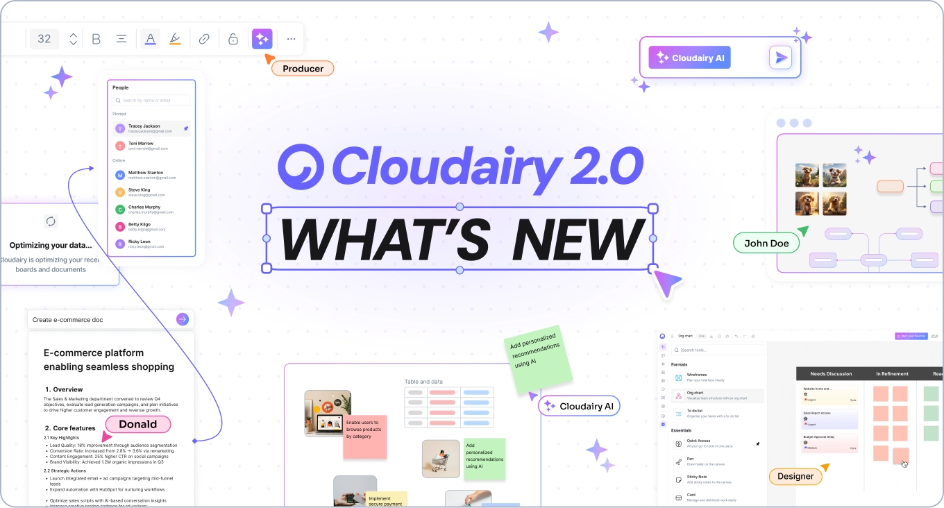
Cloudairy Blog

6 Feb, 2025

|
AWS

Introduction

Ever felt lost in a maze of code and components? With countless components and interconnected systems, it's easy to lose sight of the bigger picture. But what if I tell you there’s a way to turn this complexity into a roadmap with System Architecture Diagrams?  

Learn how to create effective system architecture diagrams by understanding key layers, protocols, and design flows. Perfect for optimizing your system design and communication.
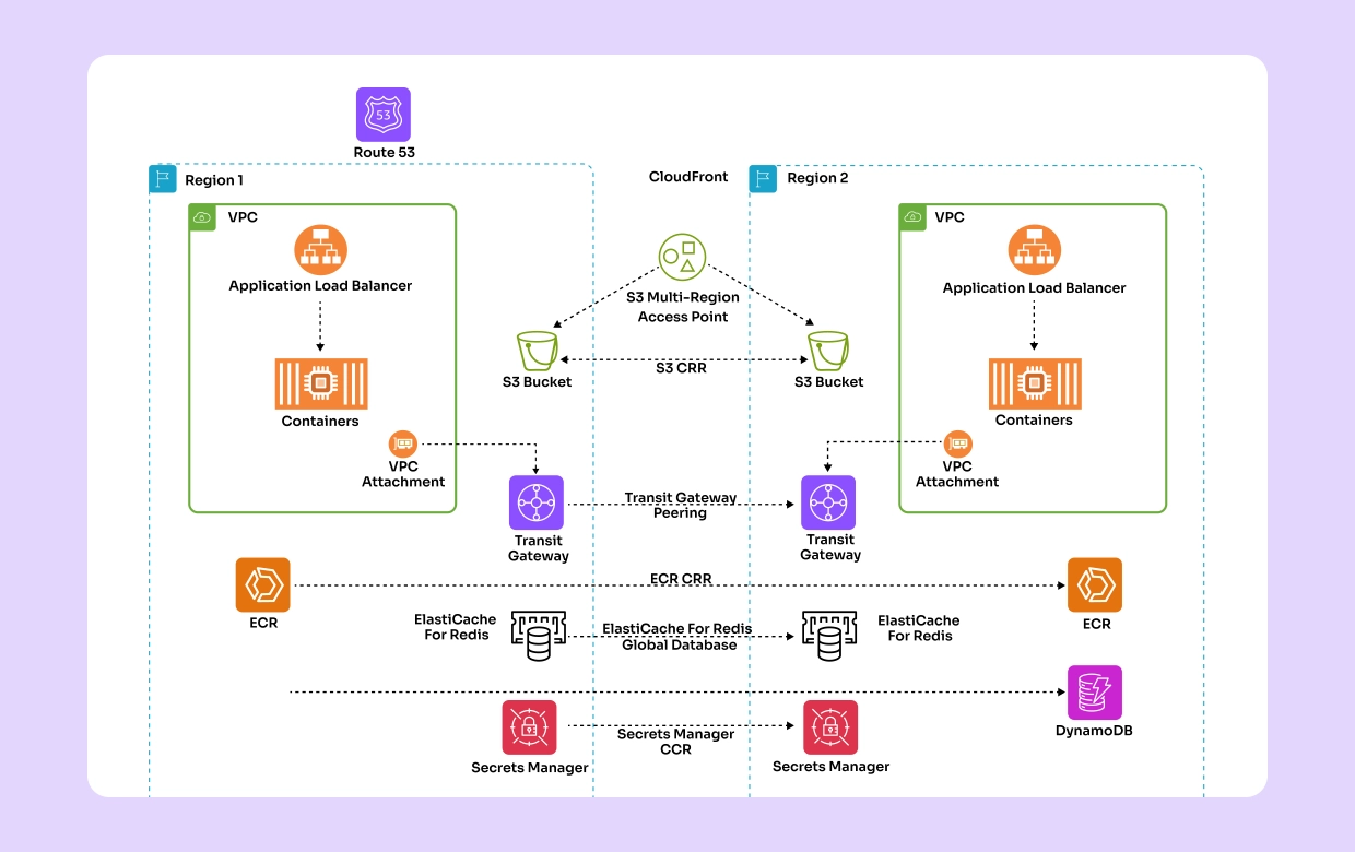
Creating effective cloud systems starts with a solid blueprint. System architecture diagrams are essential for designing, managing, and optimizing complex cloud infrastructures. This blog will take you through the entire process, from basic building blocks to advanced concepts like data flow and bandwidth considerations. 


Let’s get started!

What is a System Architecture Diagram?

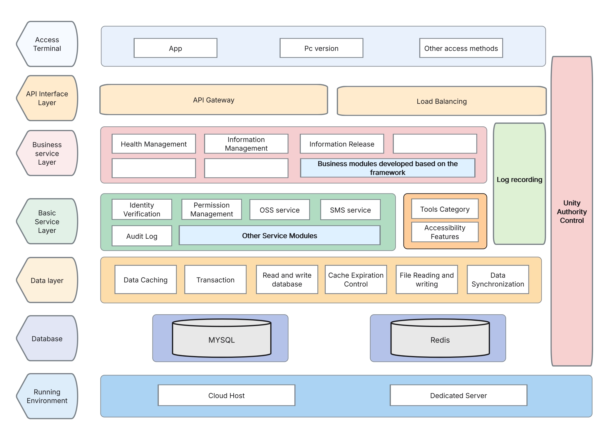
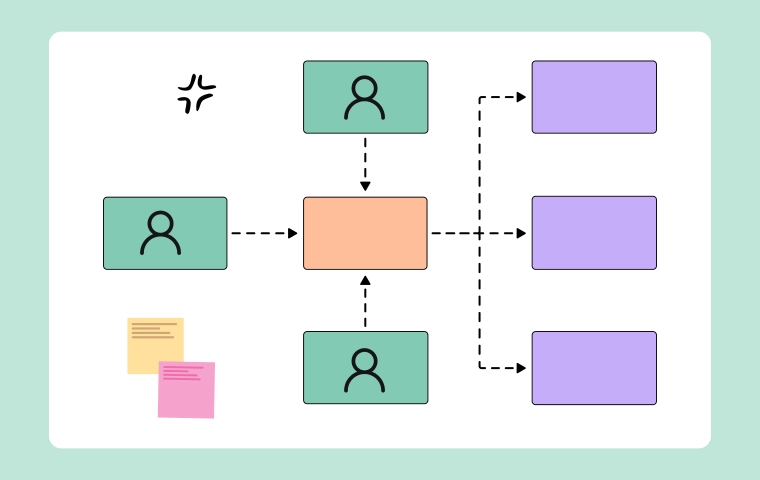
Let’s just go through the definition of the System Architecture Diagram first. System Architecture Diagram visually represents the different components in a system and how they interact. It is utilized to illustrate the organization, functionality, and essential features of the system. This blog concentrates on the design of cloud systems, providing specific information about the seven layers, protocol explanations, data and design flow, as well as bandwidth considerations.

System Architecture Diagram helps everyone involved, from developers to stakeholders, grasp the system's structure and function and contribute effectively to its development and evolution.

The Seven Layers of System Architecture

What forms the backbone of many System architectures? 

To understand the complexities of a system, we often break it down into smaller, more manageable parts. In system architecture, we use a layered approach. The fundamental layers that form the backbone of many system architectures.

Think of it like peeling an onion, each layer revealing a new aspect of the system.

Let’s understand each layer and its functionality below:

1. Physical Layer

  • Components: Hardware, servers, network devices, data centres.
  • Function: Provides the physical infrastructure for the cloud system.
  • Key Considerations: Hardware performance, reliability, physical security.

2. Data Link Layer

  • Components: Switches, MAC addresses, Ethernet.
  • Function: Responsible for node-to-node data transfer, error detection, and correction.
  • Key Considerations: Data transfer rates, error handling mechanisms, link layer protocols.

3. Network Layer

  • Components: Routers, IP addresses, subnetting.
  • Function: Manages data routing, forwarding, and addressing between nodes.
  • Key Considerations: Network topology, IP addressing schemes, routing protocols.

4. Transport Layer

  • Components: TCP, UDP.
  • Function: Ensures end-to-end communication, reliability, and data integrity.
  • Key Considerations: Transport protocols, data segmentation, flow control, error recovery.

5. Session Layer

  • Components: Session establishment, maintenance, and termination protocols.
  • Function: Manages sessions between applications, maintaining state and synchronization.
  • Key Considerations: Session management protocols, state synchronization, session recovery.

6. Presentation Layer

  • Components: Data translation, encryption, compression.
  • Function: Translates data between the application layer and the network, ensuring data is in a usable format.
  • Key Considerations: Data encoding standards, encryption methods, and compression techniques.

7. Application Layer

  • Components: Applications, user interfaces, APIs.
  • Function: Provides network services directly to end-users or applications.
  • Key Considerations: Application protocols, user experience, API design.

System Architecture Diagram

Protocol Definitions in System Architecture

Protocols are the unspoken language that devices use to communicate. Imagine a group of people speaking different languages; communication would be impossible without a common language (protocol). In the digital world, protocols ensure that devices can understand and interpret data correctly.


What do protocols do?

  • Define rules: They establish data format, transmission, and error-checking standards.
  • Enable communication: Protocols allow devices to exchange information effectively.
  • Ensure reliability: They help guarantee that data is delivered accurately and completely.

Some examples of common protocols:

  • HTTP/HTTPS: The cornerstone of the web, HTTP defines how clients and servers communicate. It handles requests for web pages, images, and other resources. HTTPS, its secure counterpart, encrypts data for added protection.
  • FTP: Designed for transferring files between computers, FTP has been a staple of file sharing for decades. However, with the rise of secure protocols like SFTP and FTPS, its use has declined somewhat. 
  • SMTP: The workhorse of email, SMTP handles sending emails between servers. It defines how email messages are formatted and routed. 
  • TCP/IP: Often referred to as the "language of the internet," TCP/IP is a suite of protocols that handles data transmission, routing, and addressing. TCP ensures reliable delivery of data, while IP handles the packet-switching process.

Ethernet: This protocol governs communication within local area networks (LANs). It defines how data is formatted and transmitted over physical cables.

Data Flow in System Architecture

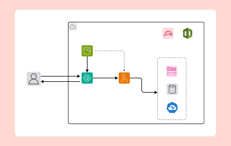
Data flow is the lifeblood of any digital system, dictating how information moves from its source to its destination. To understand this process fully, we must examine the stages involved:

  • Data Origination: Data is generated from various sources, including users, sensors, and applications.
  • Data Transmission: This phase involves the physical movement of data across networks, utilizing cables, wireless signals, or fiber optic connections.
  • Data Packaging: Data is divided into smaller packets for efficient transmission through the network. This process occurs at the network layer of the OSI model.
  • Data Routing: Packets are directed through the network to their intended destination using routing protocols.
  • Data Delivery: At the destination, packets are reassembled into their original form.
  • Data Processing: The received data is then processed by applications to extract meaningful information.


There are several challenges in managing data flow however system architecture diagrams are invaluable tools for addressing these challenges. By picturing the entire system, you can find possible slowdowns, differences, and security weaknesses.

  • Data Quality: Diagrams help pinpoint data sources and transformation points, enabling you to implement data cleansing and validation measures.
  • Data Security: By mapping data flow, you can identify sensitive data points and implement appropriate security controls.
  • Data Integration: Diagrams reveal integration points, allowing you to design efficient data integration strategies.
  • Data Volume and Velocity: Visualizing data flow helps identify high-traffic areas, enabling optimization for performance and scalability.
  • Data Governance: Architecture diagrams provide a clear overview of data ownership and responsibilities, supporting effective data governance.


By creating comprehensive architecture diagrams, you can effectively manage data flow challenges and ensure data integrity, security, and optimal performance. 

Design Flow in System Architecture

Imagine a factory assembly line; each step is crucial in creating the final product. Similarly, in software, data flows through various stages, undergoing transformations and manipulations. In this section, we are exploring several key steps of the process of designing a system architecture diagram that involves: Planning, designing, implementing, and optimizing the system. 

Planning: 

  • Analyzing Requirements: At this stage, it's crucial to identify and analyze the system's requirements, including aspects such as performance, security, and scalability. This involves understanding the functional and non-functional requirements of the system.
  • Allocation of Resources: Determining the required hardware, software, and network resources to support the system. This step involves identifying the specific technology and infrastructure needed to meet the system's requirements.

Designing:

  • Layout of Architecture: Developing a visual representation of the system, including all the layers, components, and their interactions. This step involves creating an architectural blueprint that outlines the structure and behavior of the system.
  • Selection of Protocols: Choosing the appropriate communication protocols for each layer of the system. This is essential for ensuring efficient and secure data transfer between different components of the system.
  • Mapping Data Flow: Describing and visualizing the flow of data between different components of the system. This step involves understanding how data moves through the system and identifying potential bottlenecks or points of failure.

Implementation: 

  • Setup of Hardware: Installing and configuring the physical components of the system, including servers, storage devices, and networking equipment.
  • Configuration of Software: Setting up and configuring the operating systems, middleware, and applications that will run on the system.
  • Configuration of Network: Configuring network devices, such as routers, switches, and firewalls, to establish communication links and ensure reliable data transfer.

Optimization: 

  • Tuning Performance: Optimizing the system to enhance its performance, scalability, and efficiency. This involves fine-tuning hardware and software configurations to achieve the best possible performance. 
  • Strengthening Security: Implementing robust security measures to protect the system from potential threats and vulnerabilities. This includes encryption, access control, and monitoring mechanisms. 
  • Planning for Scalability: Developing plans and strategies to ensure that the system can accommodate future growth and increased workload. This involves designing the architecture to be flexible and adaptable to evolving business needs.

These detailed steps will help build an effective system architecture that can be designed and implemented to meet the specific requirements of the organization or project.

System Architecture Diagram

Bandwidth Considerations

Imagine there is no bandwidth in any digital system! The data transmission will become unimaginably slow.. ultimately affecting the efficiency of any business. Who would want that?

​​That’s why Bandwidth is considered the lifeblood of any digital system. Let’s understand with a few points why it is crucial and how we can improve it:

  • Performance: Insufficient bandwidth leads to delays, slow loading times, and poor user experience.
  • Scalability: As your system grows, you need adequate bandwidth to handle increased traffic.
  • Cost: Overprovisioning bandwidth can be expensive while underprovisioning can lead to performance issues.

To optimize bandwidth usage, consider factors like network congestion, data compression, and quality of service (QoS). By carefully analyzing bandwidth requirements and implementing effective strategies, you can ensure optimal system performance. So let’s quickly discuss some of the major points to consider and what are the Key benefits of using architecture diagrams for bandwidth management:

  • Bandwidth Allocation: Ensure sufficient bandwidth is allocated for critical applications.
  • Bandwidth Management: Use techniques like traffic shaping and load balancing to manage bandwidth usage.
  • Monitoring: Continuously monitor bandwidth usage to identify and resolve bottlenecks.

Key benefits of using architecture diagrams for bandwidth management:

  • Identifying Bandwidth-Intensive Components: Diagrams help pinpoint system components that consume significant bandwidth, allowing for targeted optimization efforts.
  • Visualizing Data Flow: Understanding how data moves through the system helps identify potential bottlenecks and areas where bandwidth can be conserved.
  • Evaluating Network Topology: Diagrams can reveal inefficiencies in network design that impact bandwidth utilization.
  • Justifying Bandwidth Upgrades: By visualizing bandwidth consumption, diagrams can support decisions about increasing bandwidth capacity.

By combining architecture diagrams with network performance metrics, you can effectively manage bandwidth and ensure optimal system performance.

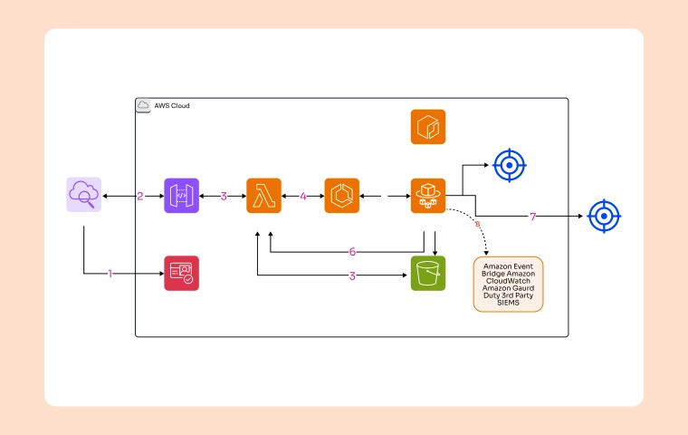
To ensure uninterrupted service and optimal performance, system architects employ advanced techniques like redundancy and load balancing.

Building Resilience: Redundancy and Load Balancing

Redundancy involves creating backups or duplicate components to prevent system failures. If one component fails, another can take over, minimizing downtime. This can be applied to servers, databases, and network connections.

  • Example: Having multiple servers running the same application ensures that if one server goes down, the others can continue to handle requests.

Load Balancing: Spreading the Load

Load balancing distributes incoming traffic across multiple servers. This prevents any single server from becoming overloaded, ensuring optimal performance and responsiveness. It also enhances system reliability by preventing single points of failure.

  • Example: A popular website might use load balancing to distribute traffic across multiple web servers, preventing slowdowns during peak usage times.

By incorporating redundancy and load balancing into system architecture, organizations can significantly improve system reliability, availability, and performance.

How Cloudairy Cloudchart Helps Design These System Architecture Diagrams

Cloudchart provides the tools and support you need to bring your vision to life. Let’s dive deep into the features of Cloudairy Cloudchart and prepare ourselves to build the masterpiece:

  1. Intuitive Interface: Cloudairy Cloudchart offers an easy-to-use drag-and-drop interface, allowing users to create and modify complex diagrams without needing advanced technical knowledge.
  2. Ready-Made Templates: Users can access a variety of pre-designed templates for different types of system architecture diagrams. These templates can be personalized to meet specific needs, saving time and ensuring consistency.
  3. Collaboration Tools: Real-time collaboration features enable multiple team members to work on the same diagram simultaneously, fostering teamwork and ensuring alignment.
  4. Extensive Library of Shapes and Icons: Cloudairy Cloudchart includes a comprehensive library of shapes and icons for various components of system architecture, such as network devices, servers, and cloud services.
  5. Advanced Customization: Users can customize every aspect of their diagrams, including layout, colors, and specific component details. This level of flexibility ensures an accurate representation of the system.

Export and Sharing Options: Diagrams can be easily exported in multiple formats, including PNG, animated SVG, PDF, GIF, and MP4 video, and shared with stakeholders or integrated into presentations and documentation.

Conclusion

Don't forget this: Creating a system architecture diagram requires deep comprehension of every layer, careful selection of suitable protocols, visualization of data flow, and taking into account design and bandwidth considerations. Cloudairy Cloudchart makes this whole process easier with its intuitive interface, collaborative tools, and a wide range of customization options. By making the most of these resources and adhering to the suggested best practices, you can develop cloud systems that are both effective and resilient, tailored to your specific business requirements.

Design, collaborate, innovate with   Cloudairy
border-box

Unlock the power of AI-driven collaboration and creativity. Start your free trial and experience seamless design, effortless teamwork, and smarter workflows—all in one platform.

icon2
icon4
icon9