Von Neumann architecture diagram template

Cloudairy
AI Workspace for Diagrams & Collaboration
Get your team started in minutes
Sign up with your work email for seamless collaboration.
Whiteboard
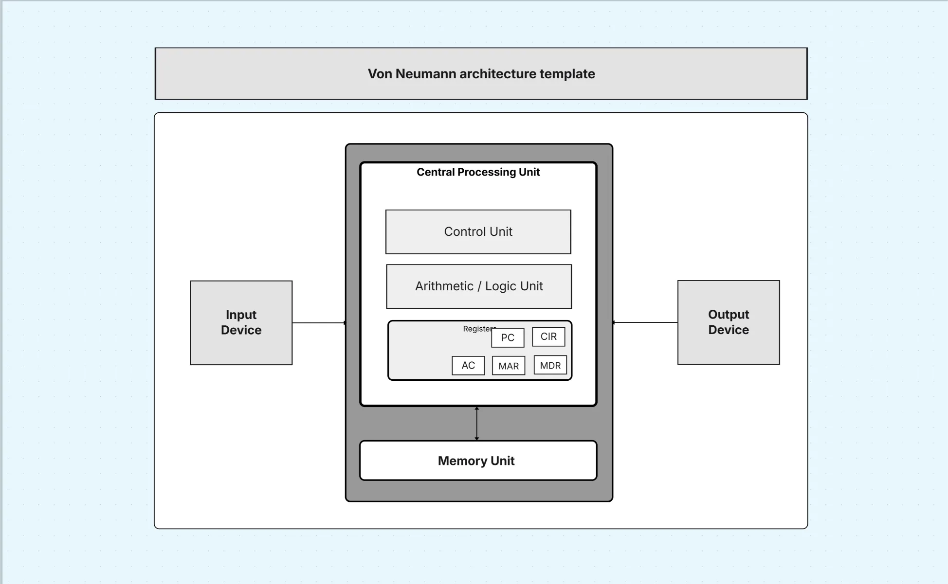
Von Neumann Architecture Diagram shows a computer system where the CPU, memory, input, and output share a single data bus, storing program instructions and data together in one common memory.
Von Neumann Architecture Diagram shows a computer system where the CPU, memory, input, and output share a single data bus, storing program instructions and data together in one common memory.
The Von Neumann architecture diagram template models the classical stored-program computer where instructions and data share memory and buses. This system architecture diagram explains how the control unit, ALU, registers, memory, and I/O coordinate to execute programs step by step. It’s invaluable for teaching fundamentals, comparing designs (e.g., Harvard architecture), and understanding performance limits such as the Von Neumann bottleneck.
This section structures your Von Neumann architecture diagram around CPU, memory, I/O, and buses so learners see fetch-decode-execute as a concrete pipeline. By making pathways explicit, the system architecture diagram connects abstract theory to measurable behavior like latency and throughput.
Create structured system design diagrams fast using Cloudairy templates
The CPU is the heart of the Von Neumann architecture diagram, directing and performing computations. Modeling CU, ALU, and registers reveals instruction flow and temporary storage, making the system architecture diagram a practical tool for reasoning about execution.
Unified memory distinguishes the Von Neumann architecture diagram from Harvard designs. Showing addressing and latency helps students grasp bottlenecks. This H3 ties memory organization to CPU efficiency so the system architecture diagram reflects real constraints.
I/O connects computation with the outside world. This H3 ensures the Von Neumann architecture diagram covers controllers and buses so the system architecture diagram links device latency to overall throughput.
Buses coordinate data, addresses, and control signals. Rendering them explicitly transforms the Von Neumann architecture diagram into a timing-aware system architecture diagram useful for labs and hardware debugs.
Use this Von Neumann architecture diagram template to teach computer organization, compare designs, or analyze embedded performance. Because the system architecture diagram is precise, it anchors labs, exam questions, and design notes with a shared vocabulary.
Tailor the Von Neumann architecture diagram template to your lab boards or simulators so students can step through execution. Keeping legends consistent makes the system architecture diagram reusable across courses and experiments.
The Von Neumann architecture diagram remains relevant for concept mastery and lab work. These examples keep the system architecture diagram grounded in real outcomes.
A Von Neumann architecture diagram is the clearest way to teach stored-program computers. By laying out CPU, memory, I/O, and buses, this system architecture diagram connects classic design to modern performance thinking. Explore Business Workflow to streamline processes and improve efficiency. Use the High-Level Architecture Diagram Template to present system components and interactions in a clear, simplified overview.
Loading subcategories...
 Manage all your work in one place
Collaborate with your team
Use Cloudairy for FREE—forever
Explore More