Technical Diagramming
C4 vs UML: Which Architecture Diagram Is Best?

AI Workspace for Diagrams & Collaboration
Get your team started in minutes
Sign up with your work email for seamless collaboration.
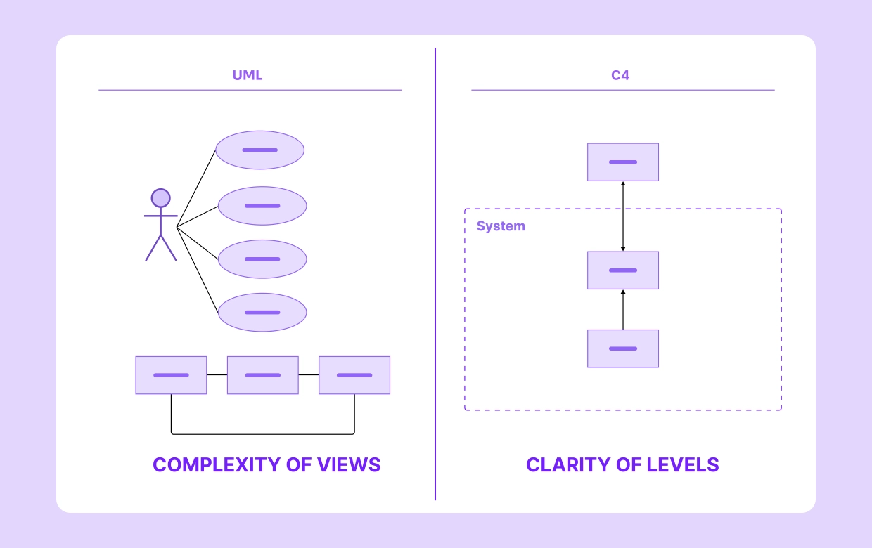
When you are building any complex application, software architecture diagrams are not just fancy documentation they become living blueprints for how systems are actually designed, developed, and maintained day to day. The two most popular choices people often discuss are UML (Unified Modeling Language) and the well-known C4 model.
The tricky part is this: many real teams find themselves debating which one feels right. Should you stay with UML’s very detailed standardized notations, or jump over to the cleaner simplicity and hierarchy of C4? The truth is, the answer always depends on your audience, scope, and exact goals.
In this article, we will walk you through UML and C4 with simple examples, weigh out their pros and cons, and give you a better sense of which one fits your project best.
Curious to try them right now? Test the Architecture Diagram Maker Tool and create both C4 and UML diagrams in just minutes.
.webp)
The Unified Modeling Language (UML) is essentially a common standard that was presented to unify the many different customizing practices that existed in software engineering. Over time, it gained detection in both educational spaces and software industries because it offers a compatible method to present systems visually and rational. One of the biggest edges of UML is its exactness and strong detail, qualities that become extremely important when projects are large and heavily technical.
UML offers developers some diagram options like outcome diagrams, class diagrams, and activity diagrams, each of which serves a distinct purpose in explaining system design and dispatch.
UML comes with dozens of different diagram types, though from my practical side, only a handful are truly useful for design work. They help us see system structure, actual workflows, and operating relations in a much clearer way.
Here are 4 key UML diagrams I often rely on:
If you are in a hurry, I’d suggest checking the UML Software Diagram Template it is been helpful for me.
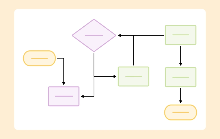
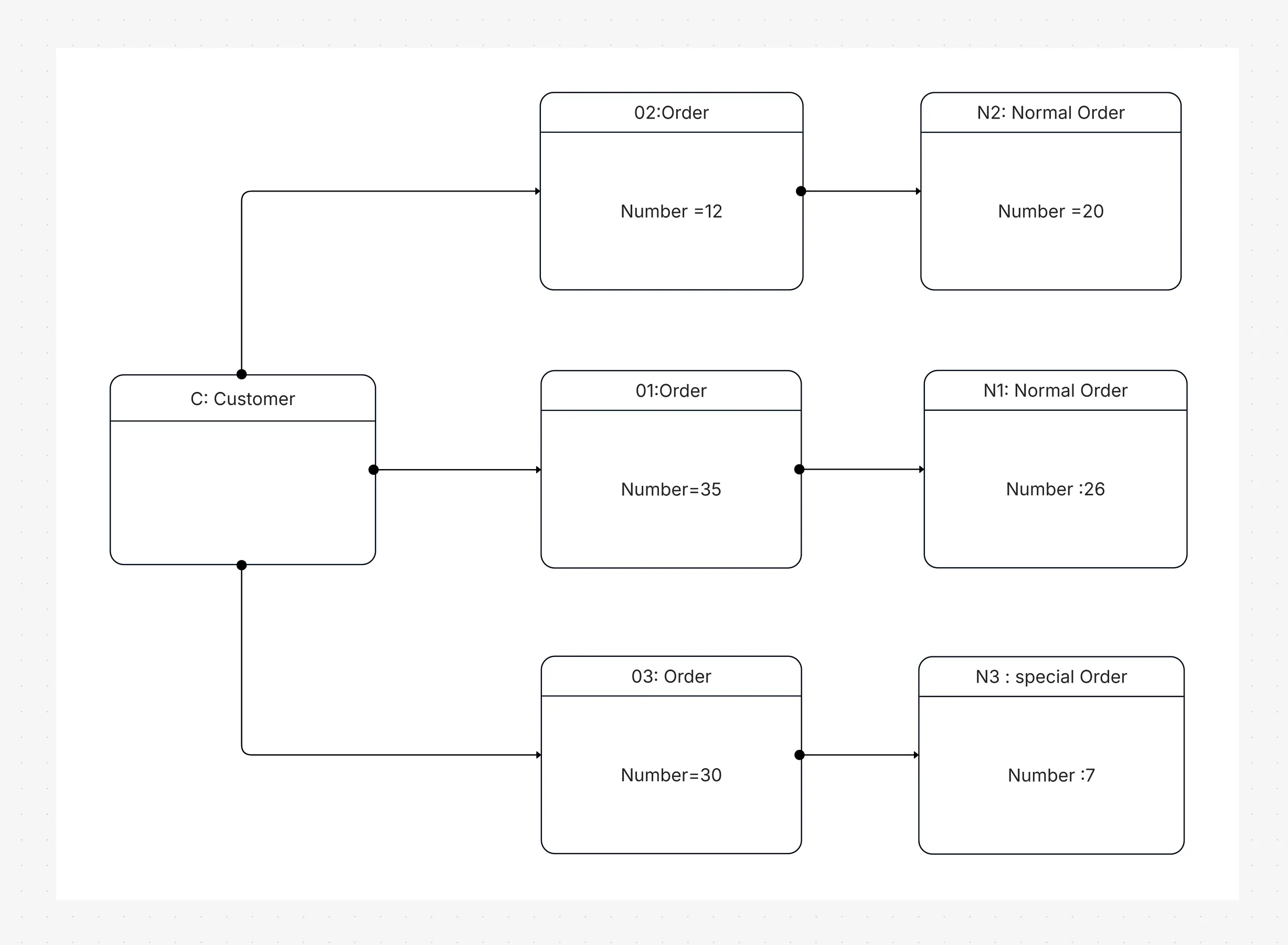
When I think about a typical e-commerce platform, clarity becomes essential. A UML sequence diagram neatly explains the checkout process step by step:
A customer confidently places an order → The order service carefully validates available stock → The payment service quickly processes the card → A friendly confirmation message goes straight back to the customer.
This kind of workflow diagram allows developers to clearly see how logic and dependencies interact. UML’s remarkable accuracy truly prevents misunderstandings and saves valuable time during testing.
The C4 approach (Context, Containers, Components, Code), thoughtfully developed by Simon Brown, was originally intended to make software architecture visualization considerably simpler and more practical for everyday developers. Instead of juggling hundreds of heavy diagram types, such as UML, C4 neatly simplifies the approach to four clear hierarchical levels that most professionals can quickly grasp. Each of these diagrams offers just the right amount of detail, depending on the audience and their immediate needs at the time.
UnlikeUML, the C4 model is not an ISO backed standard; however, its built in flexibility and straightforward clarity have made it a trusted choice among modern agile and DevOps teams who value quick, usable, and trustworthy communication.
From what I have seen in our projects, the C4 model naturally breaks a system into thoughtful layers, guiding every stakeholder our business analysts, developers, or architects to focus on their specific area when needed.
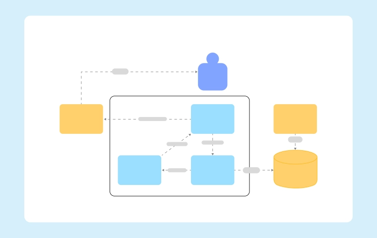
C1: Context – The first layer gives a wide perspective of how the system connects with real users, third-party services, and everyday workflows. It is especially handy for senior executives seeking to grasp how everything interacts at a high level.
C2: Containers – This stage neatly illustrates all applications, APIs, and supporting databases that form the backbone of our platform. It helps designers clearly describe deployment and design considerations to their technical peers.
C3: Parts – On this well-structured platform, the breakdown dives even deeper, carefully segmenting services, user-specific interfaces, and detailed parts managed by each individual owner. It gives the engineering team a useful and reassuring perspective on how each operational element contributes to keeping things stable overall.
C4: Code – This top layer provides a
transparent and easy-to-follow overview of the system’s codebase, with particular focus on classes, methods, and
formatting that improve readability. You are welcome to add further notes if you prefer, though our small team
typically uses a dependable C4 Model Template to ensure consistency among members.
Explore our detailed C4 Model Diagram Template to
begin working with all four practical levels.
.webp)
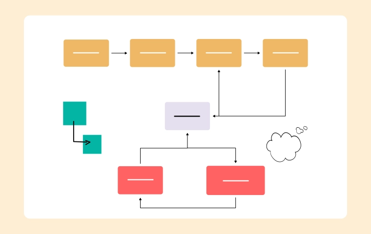
C1: Shoppers hop onto the online store to browse and pay, often linking up with trusted payment providers.
C2: Behind the scenes, the setup includes a web app, an API gateway, a place to store product info, and a payment processor.
C3: The API service packs in parts like secure sign-in, order tracking, and stock management features.
C4: Down in the code, the order section could have handy methods like createOrder() for placing orders and validatePayment() for checking payments.
Because C4 diagrams use a step-by-step layout, it’s easy to show business folks the big picture and tech people the nuts and bolts.
Throughout my career, UML has effortlessly stood the test of time as my personal favorite standard for building software architecture diagrams that make sense to me. It is detailed and formal, yet this same richness occasionally adds an extra layer of complexity I have often noticed while applying it in everyday work.
Strengths:
Limitations:
Created with honest simplicity in mind, the C4 model allows software teams, including mine, to clarify complex architecture diagrams in a much more understandable way. It is popular across agile and DevOps teams, though a few reasonable drawbacks do exist.
Strengths:
Limitations:
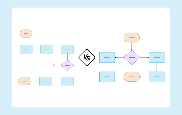
Choosing between UML and C4 depends on context. UML excels at precision, while C4 simplifies communication.
|
Aspect |
UML |
C4 Model |
|
Standardization |
Formal ISO standard |
Informal, community-driven |
|
Detail level |
Very detailed (many diagram types) |
Layered, progressively detailed |
|
Audience |
Developers, architects |
Executives, PMs, and developers |
|
Ease of use |
Steeper learning curve |
Easier to learn |
|
Best for |
Workflow and entity details |
Layered system documentation |
For more on diagram types, see Types of Architecture Diagrams Explained.
From a practical standpoint, I have found that UML and C4 each fulfill unique requirements for our project’s workflow. UML offers the technical precision many development teams rely on, whereas C4 helps speed up communication, especially in fast-moving projects.
Use UML in cases where:
Use C4 when:
Try the High-Level Architecture Diagram template for C4-style overviews.
Yes, and this combination usually works best. C4 gives you a big-picture view of layers, while UML gives you detailed documentation for each component.
For instance, a group might make a C2 container diagram
to show how a payment microservice works. They can add a UML sequence diagram to the microservice to show how
transactions go from one service to another. This mixed method makes sure that everyone understands what is
being said. The Architecture Diagram Maker from Cloudchart puts C4 and UML into one workspace.
Use Cloudchart’s Architecture
Diagram Maker to mix C4 and UML in one workspace.
Starting with the right templates honestly saves you a lot of precious time and also ensures strong overall consistency.
Templates to start with are the ones you personally feel most comfortable and confident using:
Tools that make it easy:
Most generic diagramming tools are
clunky. A purpose-built platform like Cloudchart Architecture Diagram Maker provides:
For comparisons, check our blog on Best Tools to Create Architecture Diagrams.
From my actual day-to-day work, I have seen UML and C4 act less like competitors and more like trusted partners in architecture design. UML nails the fine-grain details with precision and consistency, while C4 keeps things clear, engaging, and easy for any team to follow. When we use them together, they create a practical way to design, explain, and share complex systems without losing anyone in the process. Mixing UML for detailed engineering accuracy with C4’s big-picture simplicity helps everyone managers, architects, and engineers stay on the same page. Having a solid diagram template builds trust, reduces risk on deliverables, and keeps our agile meetings productive. Bottom line? It is not a matter of which one is “better” it’s recognizing that combined, they give balanced, efficient results every time.
Tools like Cloudchart make it cheap for my team to get going with UML and C4 diagrams, keeping things smooth from start to finish.
1.What would be the key difference between UML and C4 diagrams?
2.Between UML and C4, which one do most people find easier to learn?
3.Can the C4 model completely replace UML diagrams?
4.Why exactly would someone choose to use UML diagrams?
5.Can UML and C4 diagrams work together in a project?
Start using Cloudairy to design diagrams, documents, and workflows instantly. Harness AI to brainstorm, plan, and build—all in one platform.
Table of Contents

Introduction
 Manage all your work in one placeCollaborate with your teamUse Cloudairy for FREE—forever


 Related Articles
.webp)