hero-bg-pricing

Get your team started in minutes

Sign up with your work email for seamless collaboration.

schematic diagram
Technical Diagramming

Advanced Use: System Design & Technical Diagrams

Author
Cloudairy
By Cloudairy Team
January 10, 2026
10 min read

Introduction

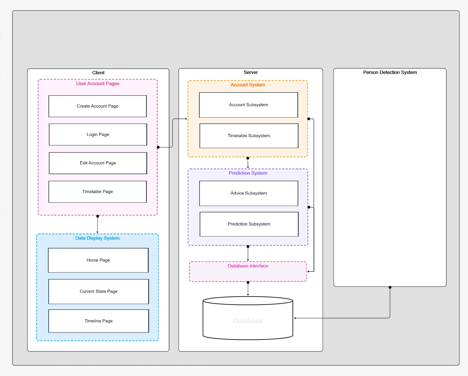
As systems grow more complex, technical diagrams become the single source of truth for design, integration, and review. From cloud architectures to embedded electronics and mechanical assemblies, precise visuals align engineers, stakeholders, and auditors.
This guide covers the advanced use of system design and technical diagrams, showing where each diagram shines, how to build them, and how to keep visuals living alongside specs, tests, and deployments.

Start fast with the Workflow & Process Diagram Maker and explore templates: Schematic, Circuit, Free Body, Technical Drawing Examples, and System Design Process Flow. See the big picture in the Pillar Guide.

Technical Drawing Examples

Why System & Technical Diagrams Matter

Diagrams compress complexity into clear, testable models. They expose integration seams, performance constraints, and failure domains before they become costly incidents.
When paired with documentation and automated checks, diagrams evolve into design contracts communicating intent, enabling code reviews, and guiding verification from prototype to production.

Key advantages:

  • Shared language for cross-discipline teams: Hardware, software, and ops align on the same shapes, signals, and interfaces.
  • Faster design iteration: Visual deltas make trade-offs explicit, reducing back-and-forth and ambiguous requirements.
  • Auditability and compliance: Tagged nodes link to specs, test evidence, and approvals for traceable sign-offs.

Core Diagram Types & When to Use Them

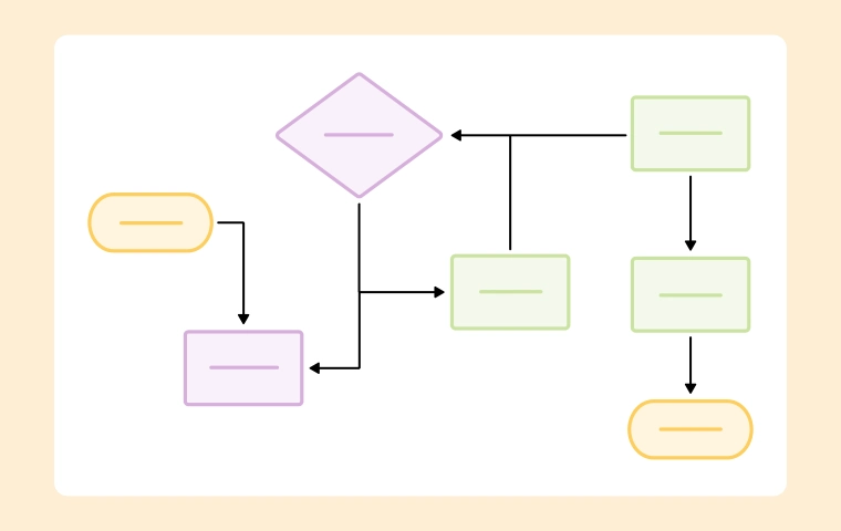
Choose the right visualization to reduce ambiguity and accelerate implementation. Each type complements the others in a full system stack.

  • System Design Process Flow: High-level architecture and data paths for services, databases, and external APIs. Great for design reviews and integration planning.
    Try the System Design Process Flow Template.
  • Schematic Diagram: Logical relationships and signals between components or subsystems. Ideal for control logic, interfaces, and system contracts.
    Use the Schematic Diagram Template.
  • Circuit Diagram: Precise electrical connections and component-level details for boards or wiring harnesses. Perfect for EE design and troubleshooting.
    Start with the Circuit Diagram Template.
  • Free Body Diagram: Forces, moments, and constraints for static/dynamic analysis in mechanical designs. Supports sizing, safety, and optimization.
    Explore the Free Body Diagram Example.
  • Technical Drawings: Orthographic/isometric views, dimensions, and tolerances for manufacturing and assembly. Critical for procurement and QA.
    See Technical Drawing Examples.

How to Create Production-Ready Technical Diagrams

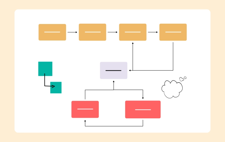
Go beyond pretty pictures. Treat diagrams as living specs that drive implementation, testing, and change management across teams.

  1. Define scope and artifacts: Decide what the diagram owns (e.g., payments service, power subsystem) and what it references via links. Avoid “everything maps.”
  2. Model interfaces first: Name inputs/outputs, protocols, and voltage or data contracts. Good interfaces shrink future refactors dramatically.
  3. Layer the details: Begin with blocks and flows, then add constraints—latency, current limits, materials, or tolerances—where they matter.
  4. Attach evidence: Link nodes to PRDs, datasheets, equations, or tests. Your diagram should answer “where’s the proof?” in one click.
  5. Version and review: Store exports alongside code and docs. Track diffs by release so design intent matches what ships.

Best Practices (and Pitfalls to Avoid)

Make your diagrams authoritative, readable, and easy to maintain throughout the lifecycle.

Do this:

  • Use consistent notation: Reuse symbols and naming across schematics, circuits, and flows to reduce cognitive load for reviewers.
  • Annotate constraints near the node: Latency budgets, torque limits, or compliance marks travel with the component, not in a distant doc.
  • Keep one diagram per concern: Separate behavior, physical layout, and process flow; link them rather than blending scopes.

Avoid this:

  • Mega-diagrams: Sprawling maps hide risk and slow reviews. Split logically and compose with links.
  • Ambiguous interfaces:Custom API” or unlabeled pins cause integration drift. Specify types, units, and bounds.
  • Diagram–reality drift: If teams don’t update visuals, retire or fix them. Stale diagrams erode trust quickly.

Example Scenarios

  • Cloud payments service: A system design flow maps auth, ledger, and webhook processors; a schematic shows retry/backoff logic; dashboards link to the same nodes for live ops.
  • Wearable device: Circuit diagram for sensor front-end and battery management; schematic for MCU interfaces; free body diagram for strap load paths during motion.
  • Factory test rig: Technical drawings dimension fixtures; schematics define PLC I/O; system flow shows data capture, traceability, and QC gates to MES.

Conclusion

Advanced system and technical diagrams turn complexity into aligned execution. By choosing the right visual, layering detail, and linking evidence, teams de-risk integration and make reviews faster and more decisive.
Build production-ready visuals with the Workflow & Process Diagram Maker and jumpstart with templates: System Design Process Flow, Schematic, Circuit, Free Body, and Technical Drawing Examples. For foundations, visit the Pillar Guide.

System Design Process Flow Template

FAQs

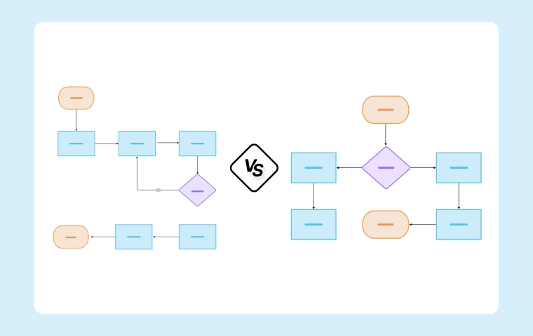
When should I choose a schematic vs. a circuit diagram?

Use a schematic to show logical relationships and signal flow; use a circuit diagram to document physical electrical connections and precise component wiring. Many teams keep both, linked.

How do I keep diagrams in sync with code and hardware?

Treat them like code: store alongside repos, require review on significant changes, and export versioned artifacts per release or ECO (engineering change order).

Can diagrams support automated checks?

Yes. Tag nodes with constraints (e.g., max current, latency). Link CI steps or scripts that validate assumptions, so failures surface before integration.

What’s the best way to handle multi-discipline systems?

Use layered diagrams: high-level system flow for architecture, plus domain-specific visuals (schematic, circuit, FBD, drawings). Cross-link nodes to keep context unified.

How detailed should I go for stakeholder reviews?

Match audience. Executives need block-level flows and risks; engineers need interfaces, constraints, and references. Keep separate views sourced from the same canonical diagram.

Ready to create smarter with AI?

Start using Cloudairy to design diagrams, documents, and workflows instantly. Harness AI to brainstorm, plan, and build—all in one platform.

Recommended for you
Using Flow Diagrams in Agile Teams
Technical Diagramming